Fastener threads are essential components in precision engineering and manufacturing. Be it on a bolt, screw, stud, or nut, these threads ensure compatibility and strength in a slew of applications, from automotive to aerospace industries and more. We’ve already defined some basic fastener thread terminology and explained the nomenclatures of Unified Inch Series threads in a previous article if you’re interested in that. Otherwise, this article will solely focus on the basics of metric fastener threads.
Disclaimer: At Wilson Garner, we mainly manufacture externally threaded fasteners like bolts, screws, and studs, so that’s where our focus is in this article. You can learn more about internal fastener threads here if you’d like.
A Quick Thread Terminology Debrief
If you’re not already familiar with some of the basic thread terms, here’s a brief overview of the most important ones you’ll need to know to understand the rest of what’s covered here.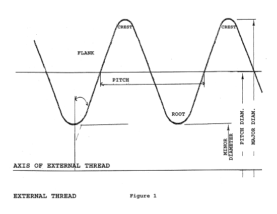
- Crest: The top of the thread
- Root: The bottom of the thread
- Flank: Connects the crest and the root
- Pitch: The distance measured parallel to the thread axis between corresponding points on adjacent threads. So, pick a spot on the thread and measure the distance to the same spot on the next thread.
- Major Diameter: The diameter of the fastener as measured at the crests of the threads
- Minor Diameter: The diameter of the fastener as measured at the roots of the threads
- Pitch Diameter: The diameter of a theoretical cylinder passing through the threads in such a manner that the distance between the crests and roots is equal.
Get more fastener terms — not just related to threads — defined here.
How to Speak Thread – Metric Version
Now, let’s start with an example that will give you a look into how we express metric threads.
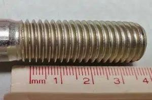
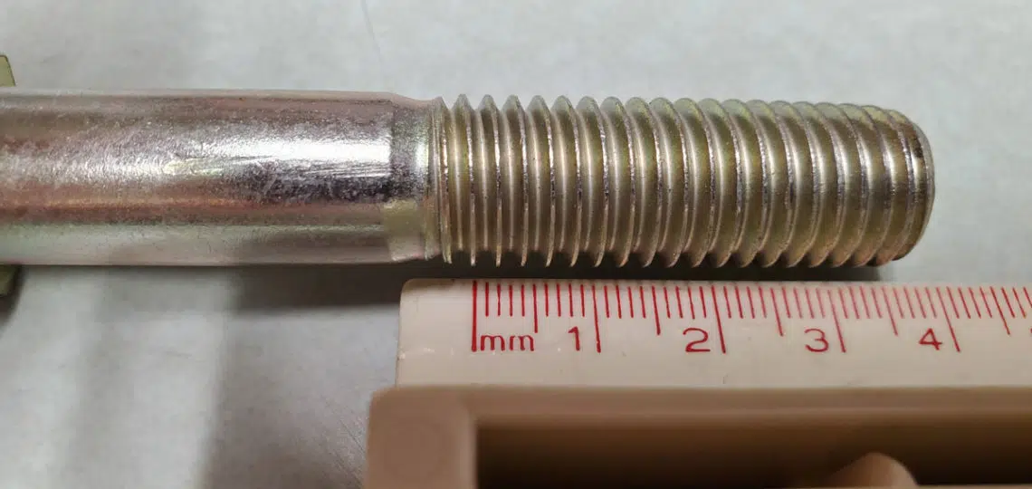
The photo above is of a metric bolt with M14 x 2.00 6g threads. Here’s a breakdown of what that means.
The “M14”: Nominal Major Diameter
The “M14” tells us that the nominal major diameter of the threads is 14 millimeters. Remember, major diameter is the diameter as measured at the widest part of the threads, and “nominal” means “basically.” In fact, the spec on this part actually calls out a major diameter of between 13.682–13.962 millimeters but nobody wants to say “M13.962,” so we just say “M14” and move on with our lives.
The “2.00”: Thread Pitch
The “2.00” refers to the thread pitch, which, again, is the distance from one point on a thread to the same point on the next thread. Here, the “2.00” tells us that the thread pitch is 2.00 millimeters. If you look at the photo, you can see this to be true, as there are 2 millimeters between the crest of one thread and the next.
Notice that this is a major difference from Unified Inch Series nomenclature, where the second number calls out threads per inch instead of thread pitch.
A Note on Fine vs. Coarse Threads for Metric Fasteners
Similar to Unified Inch threads, metric fastener threads can have fine and coarse pitches. In our example above, M14 x 2.00 is a coarse thread. The fine pitch would be M14 x 1.50.
However, in contrast to Unified Inch threads where coarse and fine pitches are fairly standard, metric fine pitches can vary depending on the specification. For the most part, coarse threads are assumed unless specified otherwise. In some specifications, the pitch isn’t even called out in the product description.
The “6g”: Thread Fit
The “6g” refers to the metric version of thread fit. 6g is the short-form expression for the external thread fit tolerance class 6g6g, which is quite common. In our article about Unified Inch threads, we talk about the 2A and 3A thread fit. In metric, 6g is roughly comparable for 2A in the Inch system.
The left number/letter combination specifies the pitch diameter tolerance and allowance, while the right number/letter combination specifies the major diameter tolerance and allowance. The numbers specify tolerance, while the letters specify allowance.
What Are Tolerance and Allowance?
Thread fits are developed using tolerances and allowances.
- A tolerance is a specified amount by which dimensions are permitted to vary for manufacturing convenience. It’s the difference between the maximum and minimum permitted limits for a given dimension.
- An allowance is an intentional clearance between mating threads. Allowances are applied to external threads, so the major, pitch, and minor diameter maximums are less than the basic size by the amount of allowance.

Metric Thread Tolerance and Allowance Examples
If you’re a visual learner, here are some diagrams and explanations to further understand tolerance and allowance.
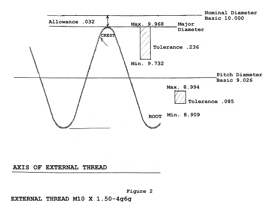
To start, let’s look at an example of a very popular thread, M10 x 1.50 6g6g:

Remember, the leftmost number/letter specifies the pitch diameter requirements, while the rightmost number/letter specifies the major diameter requirements. So, in this case, both the pitch diameter and major diameter have a tolerance of 6 and an allowance of g.
Here’s what this translates to in actual numbers:
- Pitch diameter: For M10 x 1.50 6g, 6 is 0.132mm tolerance, and g is 0.032mm allowance.
- Major diameter: For M10 x 1.50 6g, 6 is 0.236mm tolerance, and g is 0.032mm allowance.
Notice that the major diameter has more tolerance than the pitch diameter, while the allowance is the same for both.
Changing the Metric Thread Tolerance
Now, a second example, where we have a M10 x 1.50 4g6g thread:
As the numbers decrease, the amount of tolerance decreases. With a 4g6g thread fit, we have decreased the amount of tolerance for the pitch diameter and left everything else the same.
- Pitch diameter: For M10 x 1.50 4g, 4 is 0.085mm tolerance, and g is 0.032mm allowance.
- Major diameter: For M10 x 1.50 6g, 6 is 0.236mm tolerance, and g is 0.032mm allowance.
Changing the Metric Thread Allowance
Another example. This time, we’re changing the letters for a M10 x 1.50 6e6e thread:

As letters decrease (think alphabet backwards), the amount of allowance increases. So, in the above example, the tolerances for major diameter and pitch diameter are the same as 6g6g, while the amount of allowance for both pitch and major diameters has increased.
- Pitch diameter: For M10 x 1.50 6e, 6 is 0.132mm tolerance, and e is 0.067mm allowance.
- Major diameter: For M10 x 1.50 6g, 6 is 0.236mm tolerance, and g is 0.067mm allowance.
In contrast, as allowance letters increase, the amount of allowance decreases, with the “h” designation having no allowance.
Side-by-Side Comparison
For our final example, let’s look at two metric thread fit classes side by side.
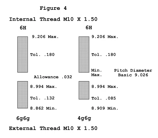
The diagram above shows the entire mated class of fit for 6g6g and 4g6g external threads with a class 6H internal metric thread. (Internal threads are expressed with capital letters. Just like Unified Inch threads, the internal metric threads generally have no allowance.)
Because of the tighter tolerance, 6H/4g6g is a tighter fit than 6H/6g6g.
Have Questions? Talk to Our Fastener Manufacturing Experts
Hopefully, this article has been a helpful introduction to metric fastener threads. If you’d like more information, we recommend taking a look at the following standards:
You can also reach out to our team to get your questions answered. We have over 70 years of specialty bolt, screw, and stud manufacturing experience. If we don’t have a confident answer for you, we can direct you to someone who will.
RELATED: Need a specialty bolt, screw, or stud? Wilson-Garner can help.